


In electric linear actuator applications, three different expressions of stroke are used.
Maximum Stroke:
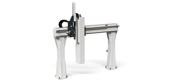
Unless otherwise indicated, any expressions of stroke in Rollon literature should be assumed to be the maximum stroke or full range of motion possible with a given linear-motion component. Sometimes called the effective stroke, this is the total distance the carriage on an electric linear actuator can move — from one end to the other. For electric linear actuators with a fixed carriage and moving profile (as with some Rollon solutions based on omega belt drives), the maximum stroke is the distance covered by the actuator end to bear the axis end effector — from the position when fully retracted position to the position when fully extended.
Working Stroke:
The Working stroke is the distance of travel needed for a given application to perform its function — so it’s a machine design parameter that potential actuator solutions need to satisfy. Typically, working stroke is the stroke value that a machine builder will use in their design work and initial communications with their component suppliers.
Safety Stroke:
Safety stroke imparts buffer zones at both ends of the linear axis to leave room for a variety of reasons: end of travel sensors and overtravel, dampers/shock absorbers stroke, as well as additional margin to help prevent the carriage from crashing into the physical actuator ends.
By default, Rollon engineers will define a maximum stroke value by adding the application’s working stroke, and:
- If available, customer defined safety stroke.
- If not available/defined, as a general rule, the linear travel achieved by four revolutions of the electric motor driving the linear axis.
For example, a linear actuator sporting a gearmotor assembly with a 25:1 ratio will have a safety-stroke value that’s only modestly different from the initial working-stroke value. While, a 3:1 ratio will have a safety-stroke value that’s a lot longer than the initial working-stroke value. This is a practical approach to setting safety stroke, as an axis fitted with a 3:1 gearmotor assembly is likely designed to move quite fast — a condition for which more safety stroke is probably warranted.

Safety Measures and Controls
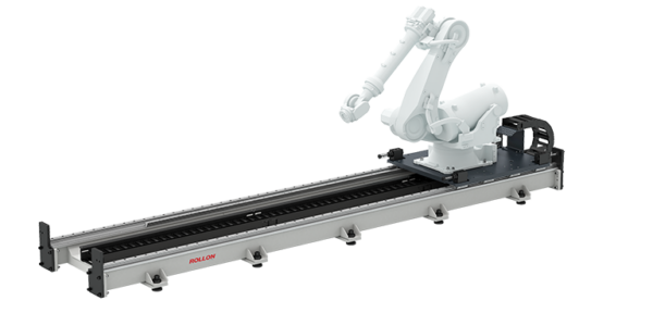
If safety stroke is exceeded, the carriage may run into bumpers at the end of the actuator and cause damage. Bigger linear-motion systems such as Rollon robot transfer units (RTUs) feature shock absorbers at their ends to minimize the damage incurred should the axis overtravel for some reason. Other system components such as proximity sensors and electronic controls specified by the machine builder or system integrator can guarantee the axis stays within the safety-stroke envelope. The simplest controls, upon receipt of sensor feedback indicating overtravel, cut power when the carriage gets too close to the end of travel. More sophisticated systems include absolute encoders and electronics to prompt a preset correction routine.
Industry Best Practices
It’s a rule of thumb to establish safety-stroke values this way. However, Rollon can adjust the safety stroke to meet specific requirements. For more information, download the Rollon white paper: Reliable linear motion.
For more information on linear systems capable of delivering a wide range of strokes, visit rollon.com. Or to enter your own application’s working stroke requirements and explore potential solutions, visit the myRollon configurator.